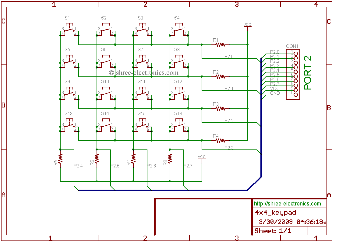
Circuit diagram for interfacing 4×4 keyboard to 8051(89s52):
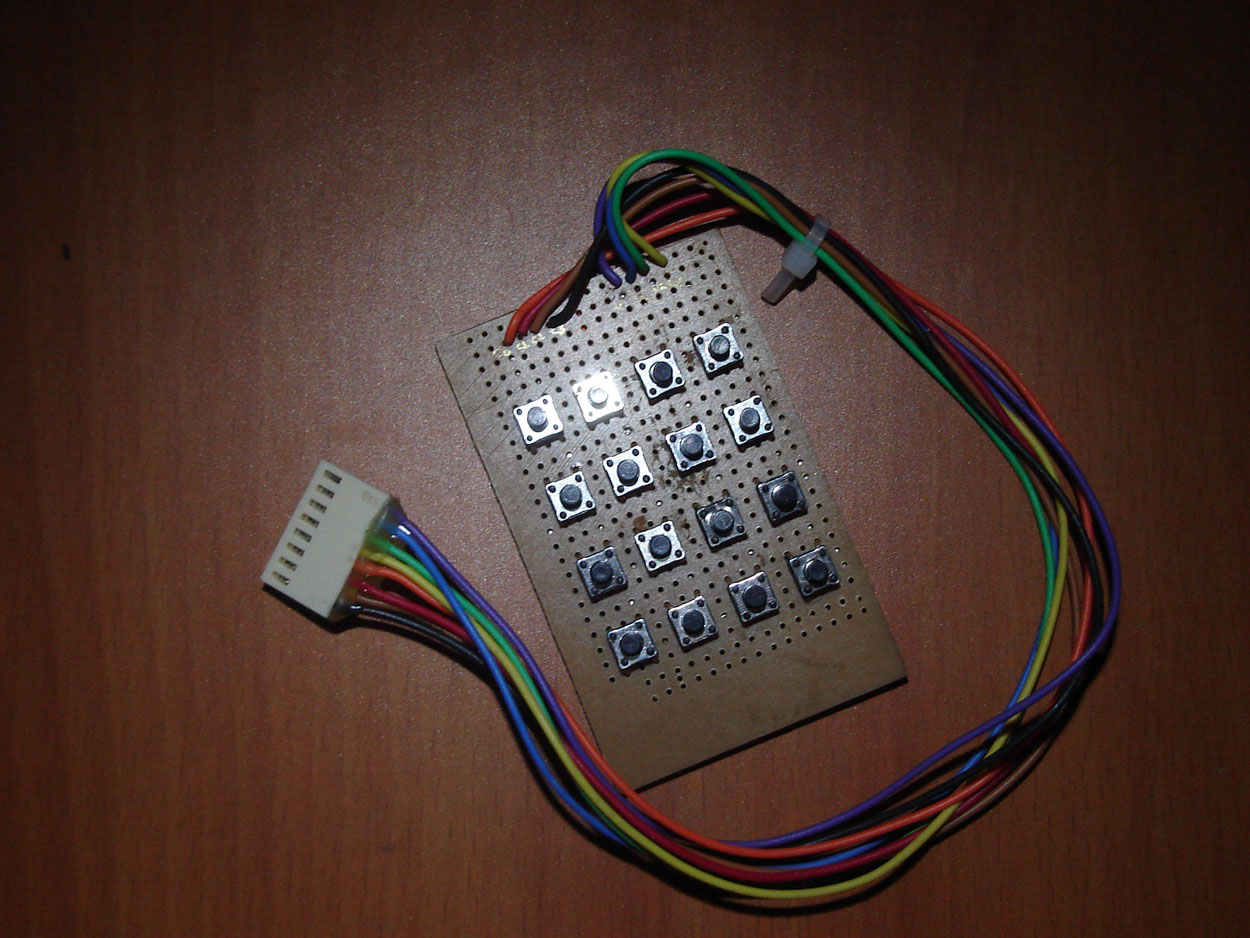
My prototype for connecting to the main development board:
The assembly program for interfacing 4×4 keyboard:
;*************************************************
;Program: Blinking LED.
;Author: Srikanth
;Website: http://shree-electronics.com/
;Description: Displays the button pressed on the
;keyboard on a 7 segment display.
;
;keyboard format: 0 1 2 3
; 4 5 6 7
; 8 9 A B
; C D E F
;*************************************************
;Declarations
rw0 equ P2.0;
rw1 equ P2.1;
rw2 equ P2.2;
rw3 equ P2.3;
cl0 equ P2.4;
cl1 equ P2.5;
cl2 equ P2.6;
cl3 equ P2.7;
;*************************************************
;Main program org 00h
ljmp main
org 30h
main: mov P2,#0ffh ;Configure input
acall scan_key ;Scan for keypress
acall display ;display the key pressed
sjmp main ;Loop
;*************************************************
;Subroutine to scan keys
scan_key:mov P2,#0ffh
clr cl0
mov a, P2
anl a,#00001111b
cjne a,#00001111b,Row0
setb cl0
clr cl1
mov a, P2
anl a,#00001111b
cjne a,#00001111b,Row1
setb cl1
clr cl2
mov a, P2
anl a,#00001111b
cjne a,#00001111b,Row2
setb cl2
clr cl3
mov a, P2
anl a,#00001111b
cjne a,#00001111b,Row3
setb cl3
ret
row0: mov dptr,#led_data
mov r6,#04h
clr c
rww0: rrc a
jc next0
sjmp over
next0:inc dptr
djnz r6,rww0
sjmp scan_key
row1: mov dptr,#led_data+4h
mov r6,#04h
clr c
rww1: rrc a
jc next1
sjmp over
next1:inc dptr
djnz r6,rww1
sjmp scan_key
row2: mov dptr,#led_data+8h
mov r6,#04h
clr c
rww2: rrc a
jc next2
sjmp over
next2:inc dptr
djnz r6,rww2
sjmp scan_key
row3: mov dptr,#led_data+0ch
mov r6,#04h
clr c
rww3: rrc a
jc next3
sjmp over
next3:inc dptr
djnz r6,rww3
sjmp scan_key
over: ret
;*************************************************
;Display subroutine
display:clr a
movc a,@a+dptr
mov P0,a
ret
;*************************************************
;lookup table
led_data:db 0fch,066h,0feh,09dh; For row1:0 1 2 3
db 060h,0b6h,0f6h,0fdh; For row2:4 5 6 7
db 0dah,0beh,0efh,09fh; For row3:8 9 A B
db 0f2h,0e0h,0ffh,08fh; For row4:C D E F
;*************************************************
end;
No comments:
Post a Comment